
Projects
Things I've designed, printed, wired up, and debugged.
Servo-powered robotic arm
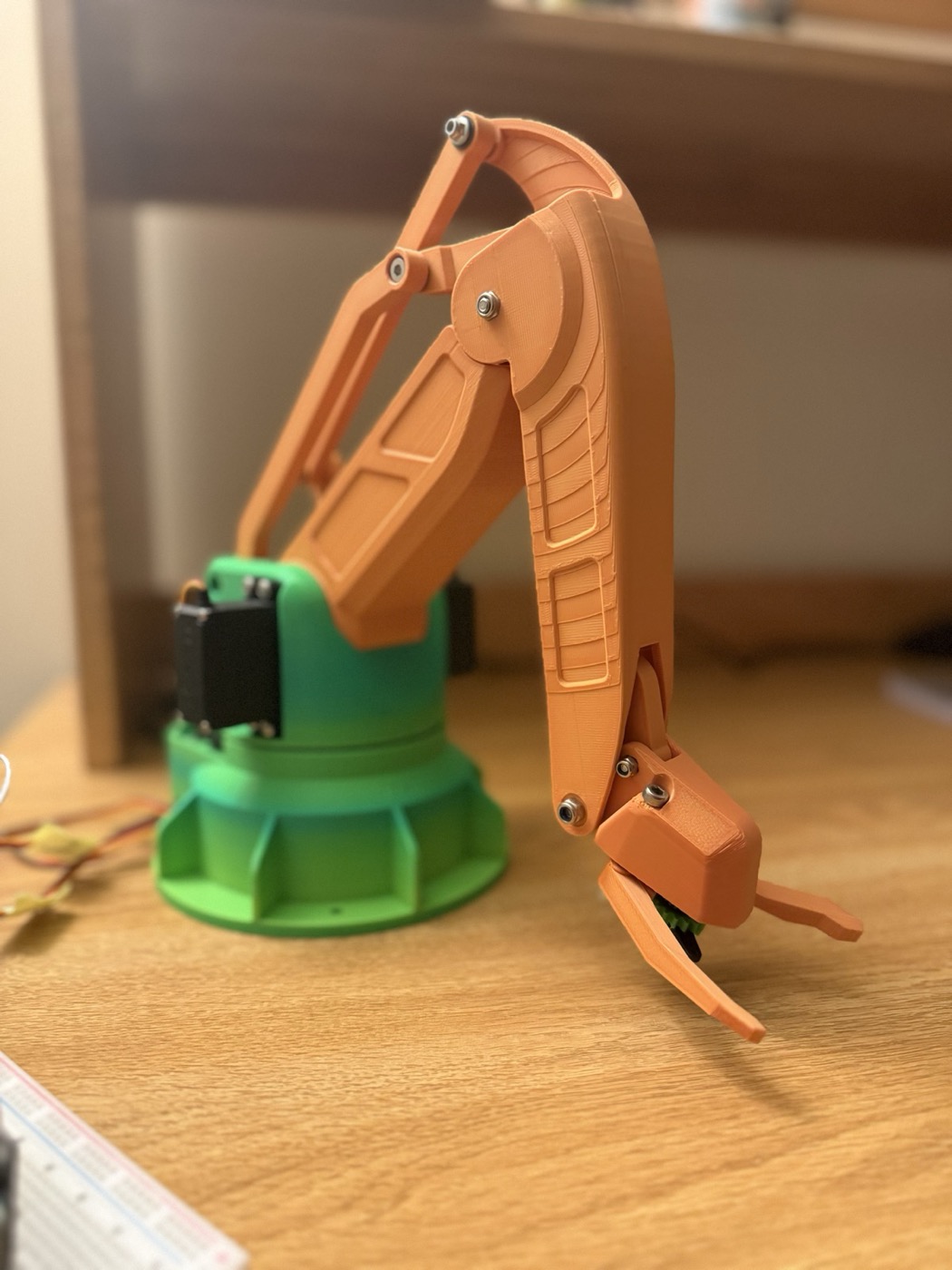
May – Aug 2026A four-joint desktop arm (base, shoulder, elbow, and gripper), each joint driven by its own hobby servo. I designed and iterated the parts in SolidWorks, printed the full assembly on a Bambu Lab printer, and checked fit, range of motion, and structural integrity before final assembly. Two thumb joysticks on a breadboard steer it, and a Raspberry Pi Pico 2 reads them and drives the servos.
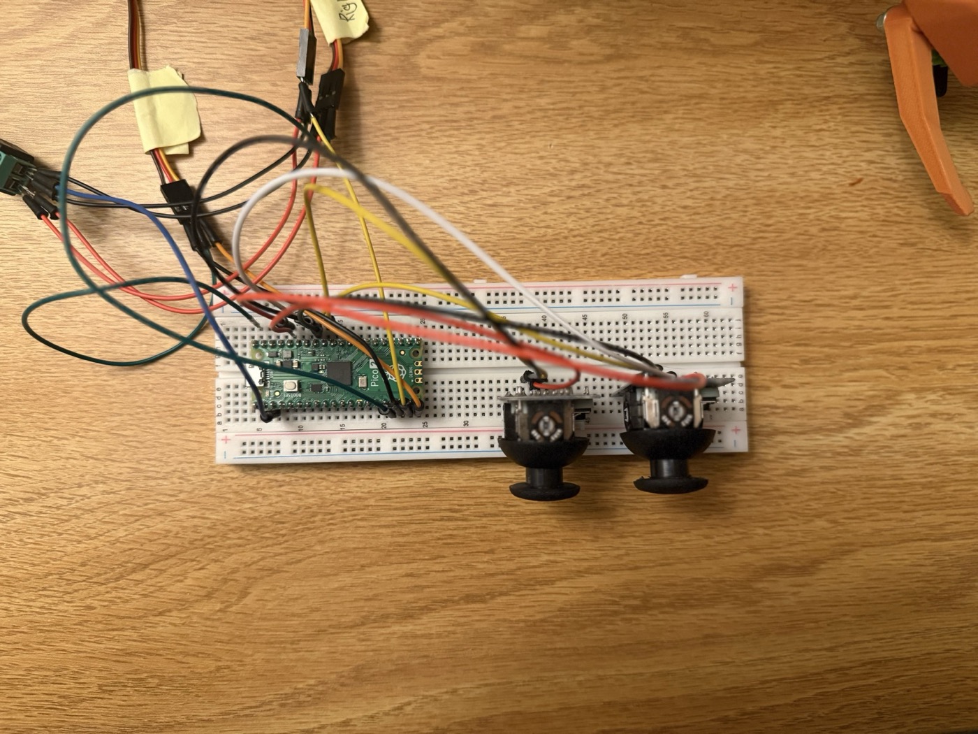
how it's wired
how it works
- Each joystick axis is a potentiometer, so pushing the stick changes a voltage that the Pico reads with its analog-to-digital converter.
- The Pico turns those readings into a target angle for each joint.
- A hobby servo sets its angle from the width of a pulse repeated about 50 times a second, roughly 1 ms at one end of its travel and 2 ms at the other. The Pico generates a separate PWM signal for each of the four servos.
- I calibrated each servo's endpoints and the motion sequencing through repeated test runs, so the joints move to the same place every time and stay inside the range the printed parts allow.
what went into it
- Several design revisions in SolidWorks, refining part geometry and the assembly between prints.
- Printing the whole arm on a Bambu Lab printer and test-fitting before final assembly to check range of motion and structural integrity.
- Writing down each iteration and test result to guide the next round of mechanical and control changes.
Tabletop board game
Oct – Dec 2025A fully functional tabletop game built for two clients by a three-person team. I led it from start to finish. The board is two mirrored halves, one per player, laser cut from MDF with finger-jointed walls. Each half is split into scoring zones worth +1 to +5, with a goal pocket at the far end. The pucks, blockers, posts, and goal arch are all 3D printed.
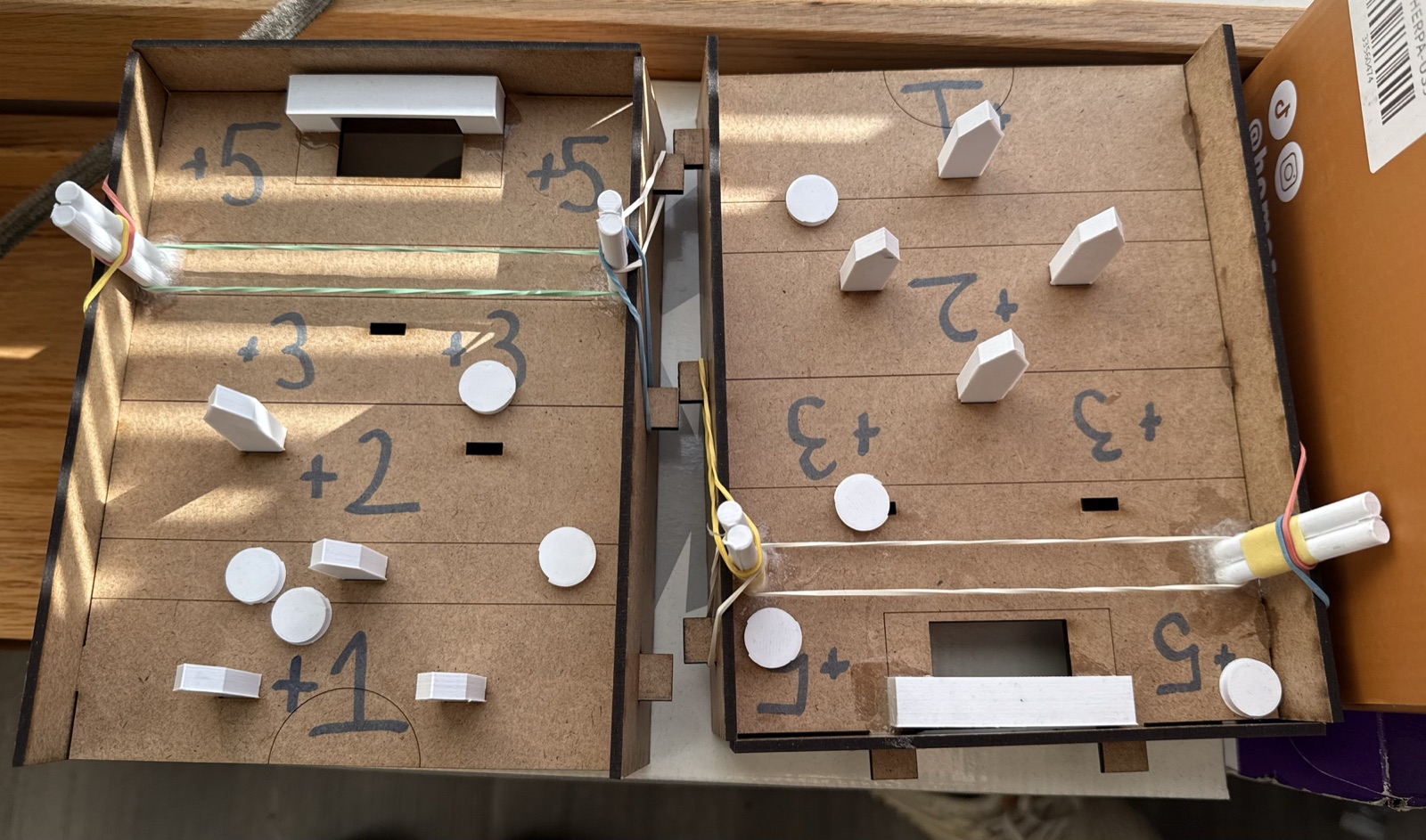
how the board is laid out
how we built it
- Produced the complete CAD package (part models, assemblies, and manufacturing drawings) in SolidWorks and AutoCAD.
- Ran prototyping cycles with 3D printing and laser cutting, reworking geometry and assembly around playtesting feedback and the places parts failed.
- Ran our design reviews, documenting decisions, test outcomes, and revisions until we landed on a prototype the clients approved.